 It was necessary to view an output from my camera chip on a common TV.
I have tested this circuit only with Merkur TV type, but I hope it'll do
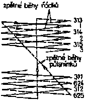
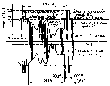
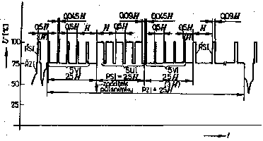
for others as well. Next timing pictures are taken from a textbook and
that's the only documentation I had.


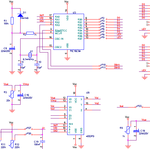
Next picture shows a part of circuit which makes video signal. The principle
of that circuit is following - the output Vo2 is periodically connected to
voltage levels Vout and Vimp that corresponds to a pulse voltage
and to the black level voltage. All is driven by PIC16C84.
Vo1 signal is the amplified output signal from camera chip.
| signal | description | range |
|---|---|---|
| Vout | black colour level | trimmed by R9 0 .. 5V |
| Vimp | sync pulses level | trimmed by R3 0 .. Vout |
| Vo1 | amplified output signal from camera chip | >= Vout |

It is possible to get all schematic (50k) of the test board. There is documentation (27k) in OrCAD for Window$ and source code (3k) for PIC16C84.
|
|
|